This Website is not fully compatible with Internet Explorer.
For a more complete and secure browsing experience please consider using Microsoft Edge, Firefox, or Chrome
The NAFEMS Metallic Additive Manufacturing Focus Team [1], a part of Manufacturing Process Simulation Working Group [2], is devoting considerable effort to developing a suite of challenge problems that encapsulate the complexities of simulating the additive manufacturing (AM) process. These problems are designed to test both analysis engineers and their software tools.
The target of the first challenge problem is to qualitatively predict the observed outward buckling phenomenon caused by the additive manufacturing process.
The reader is encouraged to simulate the phenomenon based on the included and referenced information, and then share their experience with the team using the following link.
Recently, the Team offered practical advice in the booklet "How to – Model the Additive Manufacturing Process [3]. This guide, in addition to describing the challenge problem, can assist readers in understanding the process.
The benchmark problem highlights the susceptibility to buckling in thin-walled structures due to the AM process. This buckling phenomenon is evident in the tube-like components shown in Figure 1, where the walls demonstrate an outward distortion after the tube is separated from the substrate post-printing. G. Vastola et al. [6] have investigated this effect in similar geometries and found that the buckling analysis results align with the observed deformations, strongly supporting the identification of this deformation as buckling.
Further details on this phenomenon can be found in the Methodology and Validation of Rapid Prediction of Distortion for Powder-Bed Additive Layer Manufacture” [4] conference paper and in the “Distortion prediction and compensation in selective laser melting” [5] article for Ti6Al4V.
The Team has confirmed that the proposed geometry exhibits buckling across a broad range of materials and process settings. It is, however, impractical to test every possible combination, which is why this challenge is presented as a qualitative manner. In all experimental and numerical settings evaluated, buckling has indeed occurred. For companies and institutions engaged in thin-walled metal additive manufacturing, the ability to predict this buckling phenomenon is crucial when selecting simulation software and methodologies.
To capture the buckling effect in the manufacturing process simulation, various methods may be employed. These include the general sequentially coupled thermal-mechanical simulation, the more straightforward inherent strain approach [3], or an approach that utilises a calibrated analytical thermal model integrated within the structural Finite Element Analysis [4], [5]. The group has explored the latter two methods in their research.
Buckling manifests progressively during the additive manufacturing (AM) building process, leading to the component being in a permanent post-buckling state. Consequently, it is essential to conduct the process simulation with geometric non-linearity enabled.
From the Team's experience, the resolution of the mesh and the selection of the appropriate element type significantly influences the simulation outcomes. Shell elements or continuum shell elements are recommended; however, it has also been demonstrated that hexahedral solid elements, when appropriately chosen, can effectively predict buckling. Software packages that conceal the meshing step might struggle with accurate buckling prediction.
Correctly setting the boundary conditions is crucial for accurately simulating the separation of the specimen from the substrate. The simulation should ideally include at least two phases: the building process, where the part is affixed to the baseplate of the laser powder bed machine, followed by a step to sever it from the substrate. Additionally, achieving an effective simulation also depends on maintaining a balanced ratio between the actual and simulated layer heights.
The following two sections will introduce the details of the observed buckling phenomenon for both 316L stainless steel and Ti6Al4V. The two main aspect connecting these observations is that they share the same tube type test specimen geometry and the observed results are also analogous in nature, with AM Ti6Al4V exhibiting the effect in a more pronounced way.
The buckling phenomenon for 316L stainless steel
To provide experimental grounds for posing the benchmark, twelve stainless steel (316L) specimens have been built with an EOS M290 (400W) machine (Figure 1).
Figure 1. Twelve steel specimens that have been built at TWI with an EOS M290 (400W) machine.
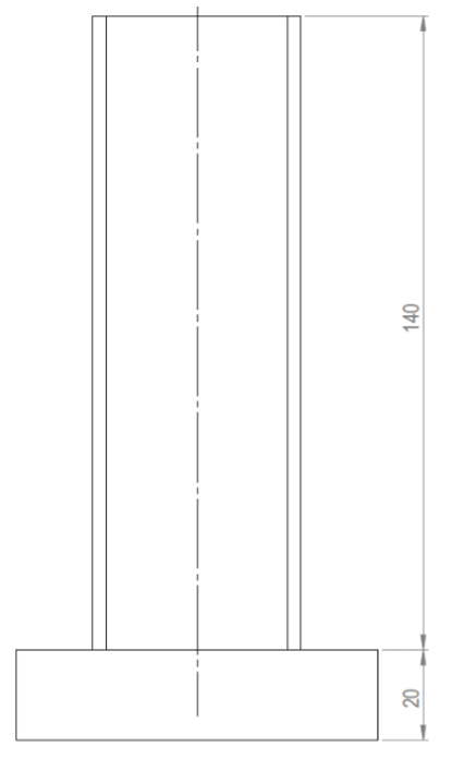
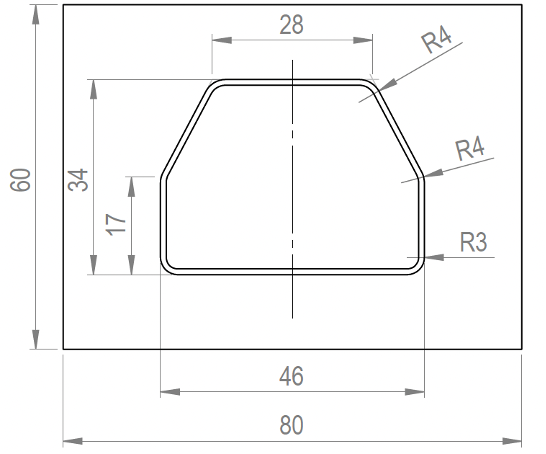
The overall dimensions of the tube type test specimen are: 140 mm height and 10 mm base plate thickness, 46 mm x 34 mm bounding dimensions for the cross section, and 1 mm wall thickness. Figure 2 displays a sketch of the tube type test specimen. The test specimen represents a simplified section of an additively manufactured bicycle frame. The gometry is available as a downloadable file in "step" format through the following link.
Figure 2. Dimensions for the tube type 316L stainless steel test specimens.
The stainless-steel powder “EOS StainlessSteel 316L” has some of its material properties included in the material data sheet [7]. The following printing parameters have been set when printing the twelve tube-type test specimens (further details can be found in the Appendix):
Total printing time: 39 hours and 27 minutes,
Start Z: 0.04 mm, End Z: 144 mm, height: 143.96 mm (3599 layers),
Layer thickness: 0.04 mm,
Beam offset: 0.08 mm, platform temperature: 20°C,
Laser Temp.: Max. Temp. 26.4 °C / Min. Temp. 25.2 °C,
Exposure duration per layer: 30 seconds,
Substrate was 316L dimensions as shown with thickness 20 mm.
Figure 3 presents the optically measured residual deformations of 316L stainless steel specimens, assessed via laser scanning. The figure shows the backside of the specimens. The distortion was evaluated using STL files from the reference geometry intended for the printing process and from individual scans of the twelve specimens post-removal from the substrate. The average outward distortion at the middle of the backside is approximately 0.12 mm, derived from an approximate evaluation of the displayed measurements. Although all twelve specimens demonstrated the buckling phenomenon, the authors have chosen to disclose only six plots. This selection was due to the challenges in aligning the reference and distorted STL scans, which often complicated the derivation of reliable results.
Specimen 1 (max. distortion at the centre around 0.15 mm)
Specimen 2 (max. distortion at the centre around 0.15 mm)
Specimen 3 (max. distortion at the centre around 0.15 mm)
Specimen 4 (max. distortion at the centre around 0.10 mm)
Specimen 5 (max. distortion at the centre around 0.085 mm)
Specimen 6 (max. distortion at the centre around 0.09 mm)
Figure 3. Measured residual deformations for the 316L stainless steel specimens (backside visible, positive numbers and warmer colours signal outward deflection).
The buckling phenomenon for Ti6Al4V
The buckling-like thermal distortion effect has also been observed in AM Ti6Al4V. The extent of distortion can be quantitatively estimated by the ratio of yield strength to Young's modulus, which is notably high for Ti6Al4V. This leads to the max. outward distortion of the tube being in the range of 0.2 mm, which is notably higher than the app. 0.12 mm observed for the steel specimens. According to the Team's experience, variations in printing process parameters do not fundamentally alter the observed buckling behaviour.
The titanium specimens were fabricated using a Renishaw AM250 SLM (200 W) machine, adhering to the default process parameters established for Ti6Al4V [8].
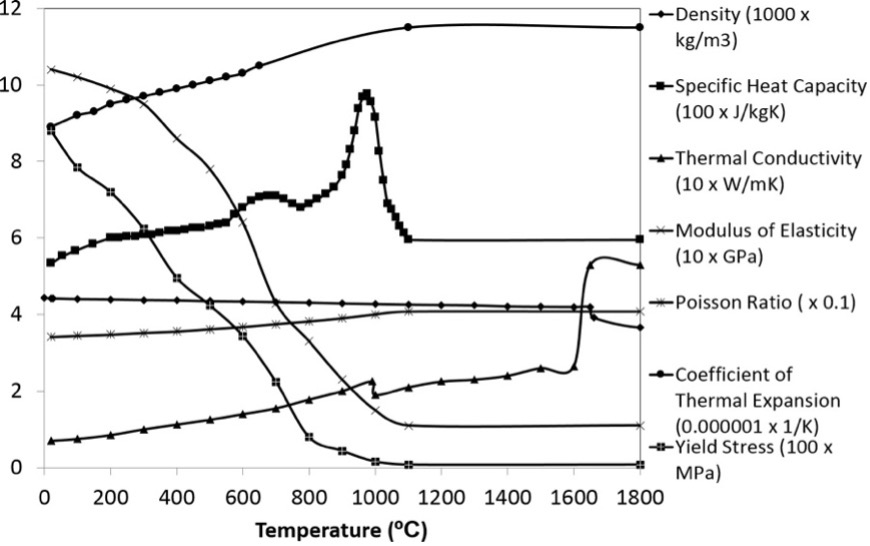
Figure 4 illustrates the temperature-dependent material properties of Ti6Al4V, with additional details included in the powder's data sheet [8]. These properties in Figure 4 are provided for further reference. The authors have effectively predicted the buckling using the inherent strain approaches [3], which does not require temperature-dependent material properties.
Figure 4. Temperature dependent material properties for additively manufactured Ti6Al4V.[4]
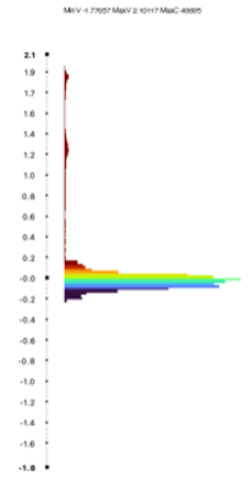
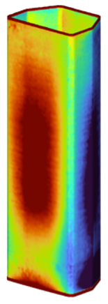
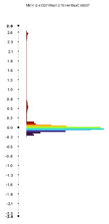
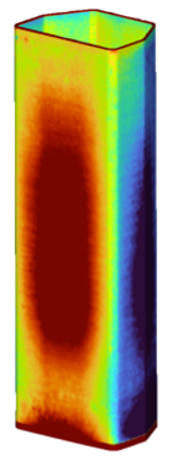
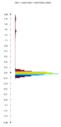
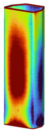
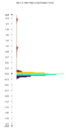
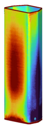
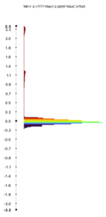
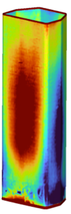
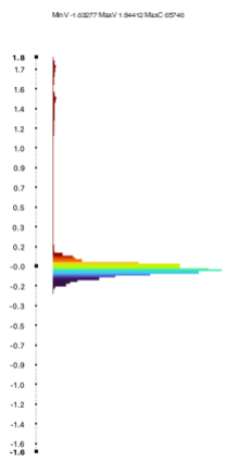
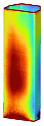
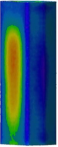
Figure 5 displays the measured (scanned using optical 3D scanning technology) and simulated residual deformations of the tube, after it has been cut from the substrate. The measured outward distortion at the middle of the backside is approximately 0.20 mm.
Figure 5. Measured residual deformation on the left (the scans were made after the part had been cut from the baseplate), simulation results on the right (in mm) for Ti6Al4V (showing the face that is 46mm wide) [4].
[2] Manufacturing Process Simulation Working Group, NAFEMS. Available: https://www.nafems.org. [Accessed: Dec. 8, 2023].
[3] S. Van-Der-Veen, P. Hurrell, T. London, M. Megahed, J. Rome, and B. Saunders, How to – Model the Additive Manufacturing Process. 1st ed., NAFEMS, 2022. Available: https://www.nafems.org.
[4] S. Afazov, W. A. D. Denmark, B. L. Toralles, A. Holloway, and A. Yaghi, "Distortion prediction and compensation in selective laser melting," Additive Manufacturing, vol. 17, pp. 15-22, 2017. ISSN 2214-8604. Available: https://doi.org/10.1016/j.addma.2017.07.005.
[5] A. Yaghi, S. Afazov, A. Yaghi, A. Holloway, W. Denmark, B. Lazaro Toralles, A. Okioga, "Methodology and Validation of Rapid Prediction of Distortion for Powder-Bed Additive Layer Manufacture," in Proc. NAFEMS World Congress, Stockholm, Sweden, June 12, 2017. Available: https://www.nafems.org.
[6] G. Vastola, W.J. Sin, C.-N. Sun, and N. Sridhar, "Design guidelines for suppressing distortion and buckling in metallic thin-wall structures built by powder-bed fusion additive manufacturing," Materials & Design, vol. 215, 110489, 2022. ISSN 0264-1275. Available: https://doi.org/10.1016/j.matdes.2022.110489.
 machine.")